Unbox and Put Your FRAME Together
This tutorial is the first guideline show you how to unbox the Frame microscope. Please go through the steps before you power on the microscope for the first time.
Warning: Powering on the microscope without removing the transport lock may cause irreversible damage to the microscope!
Remove the outer box and take out the components
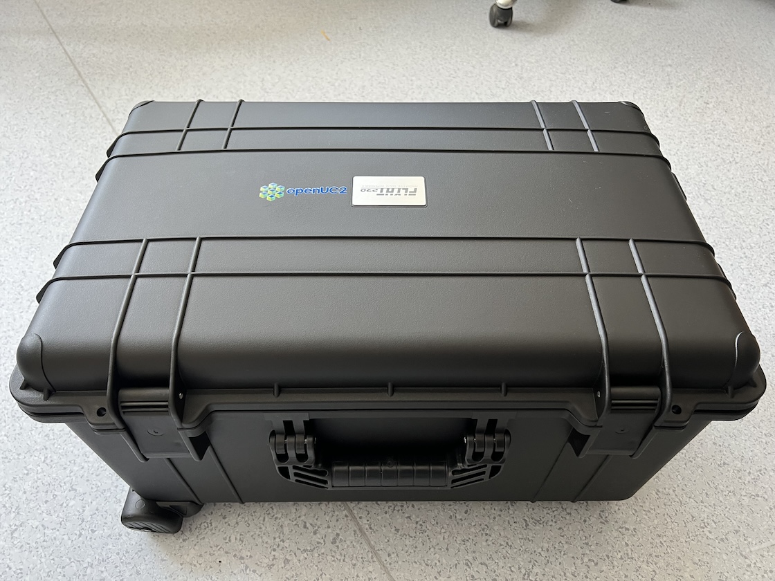
After open the outer box, you will find the safe box contains the microscope.
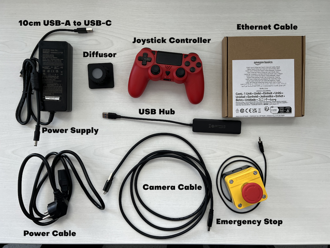
 In the second small package, it should be some extra accessories for the microscope as shown here
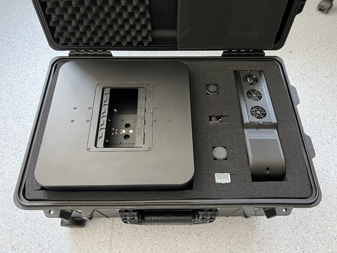
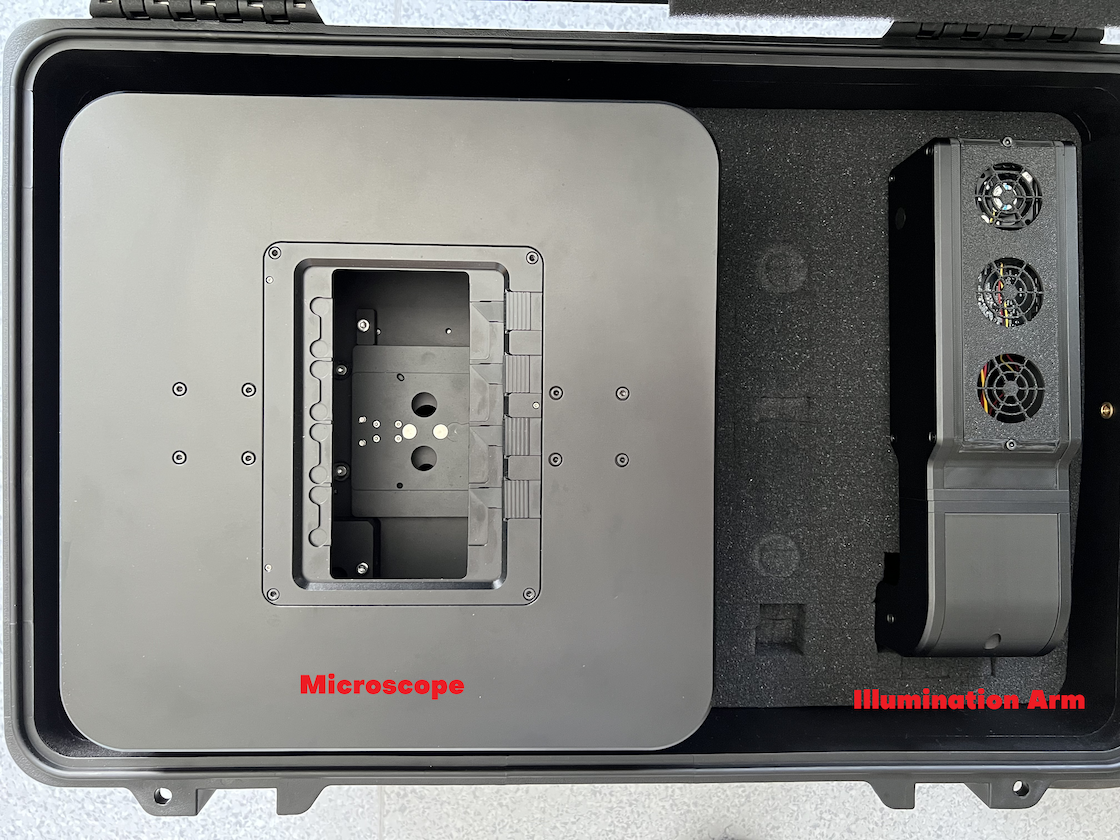
 Open the safe box, left side is the microscope and right side the illumination arm and in between sit some small accessories.
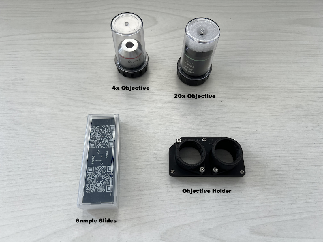
 Take out the accessories fist
 Then remove the first layer of the protection foam, and take out the illumination arm.
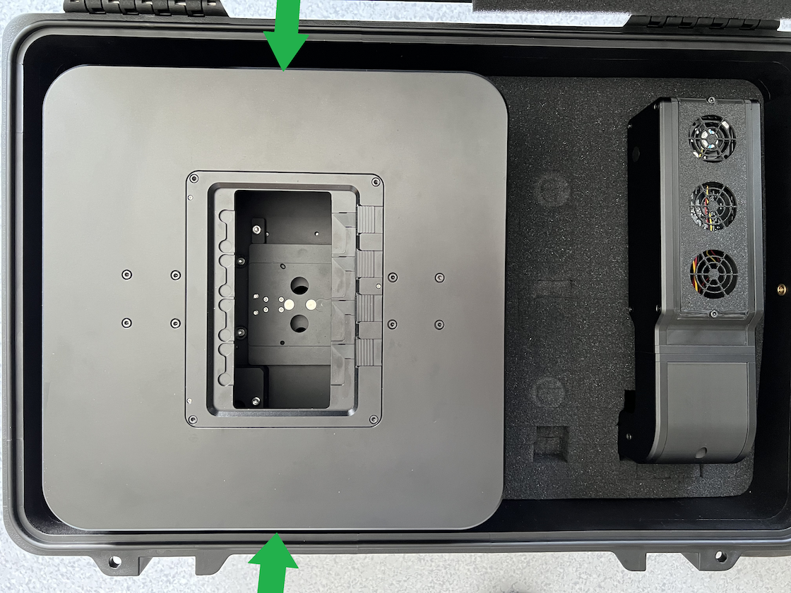
 After take out the illumination arm, the rest layers of foam can be removed from the box. Put hands to the side of the microscope (green arrow side), find the bottom surface of the stage. This surface is a solid metall surface, apply force to this surface to uplift the microscope.
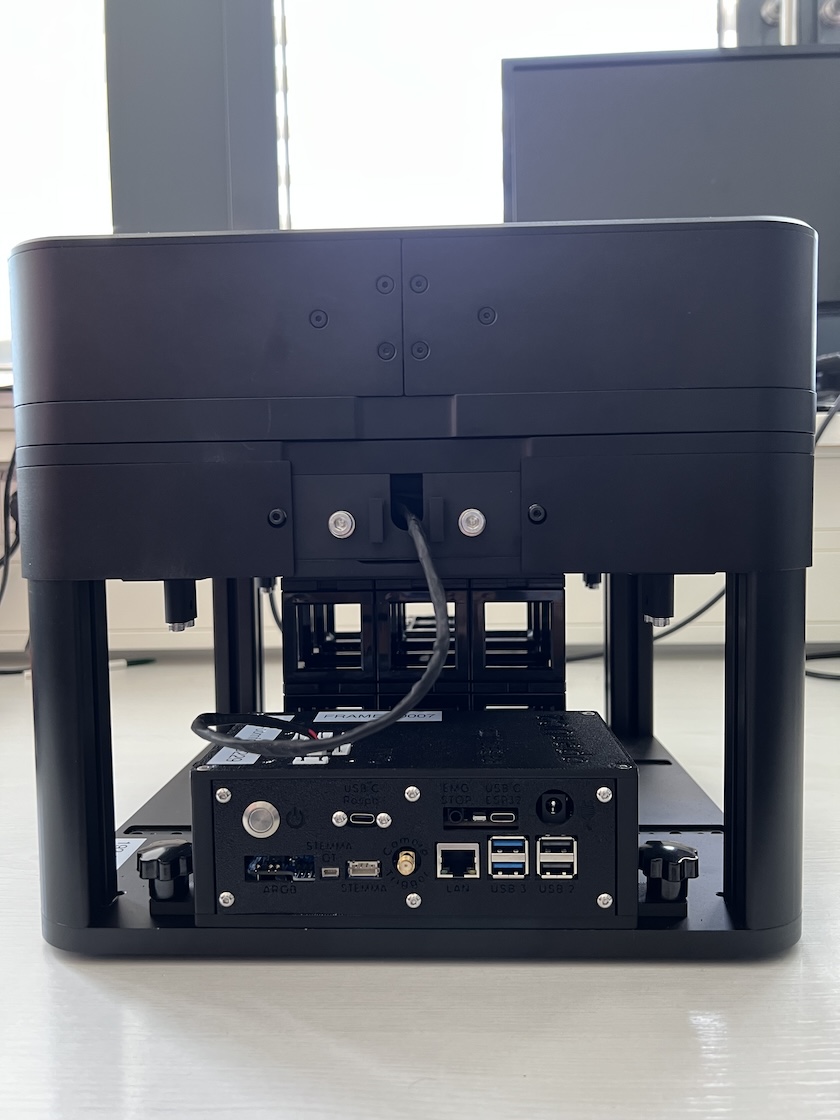
Now the microscope can be easily move to a flat table.
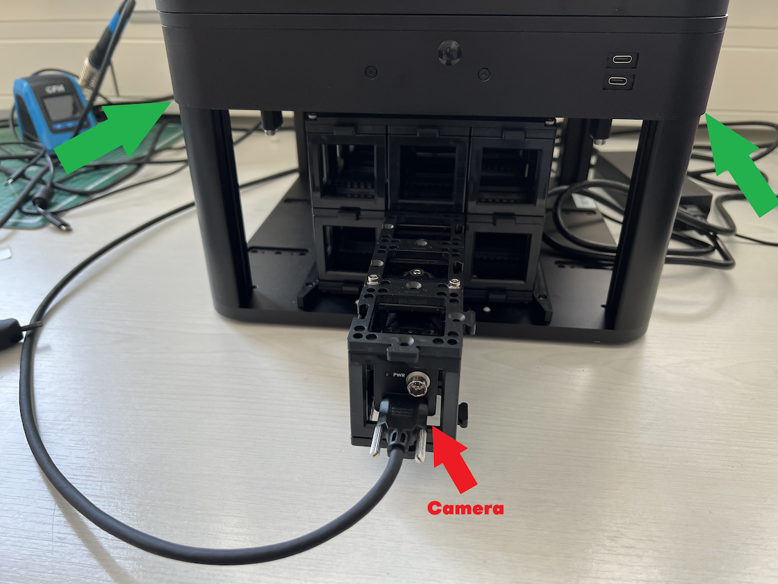
Warning: Be careful with the extended optical module, the camera sits in the last cube, don't put on force to the camera.
Remove the transport lock
The micorscope is mounted with transport lock for transportation. Remove the sample holder to find the trasnport lock.
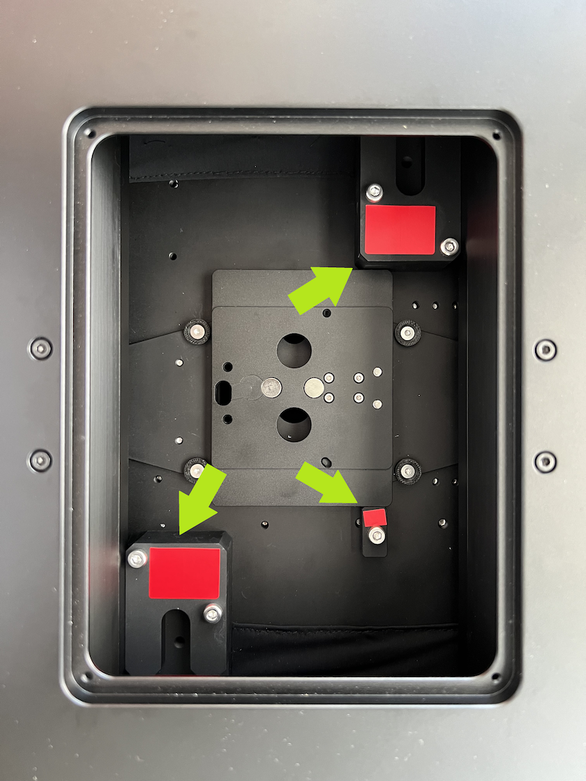
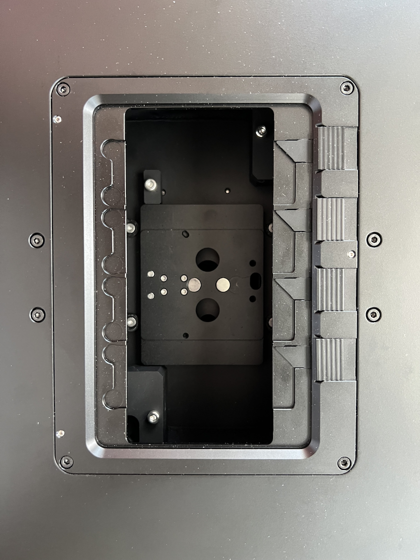 The 3 pieces of locks fix the axises and are labeled in red. Unscrew the screws and remove the blocks completely. After remove the transport lock, mount the sample holder back.
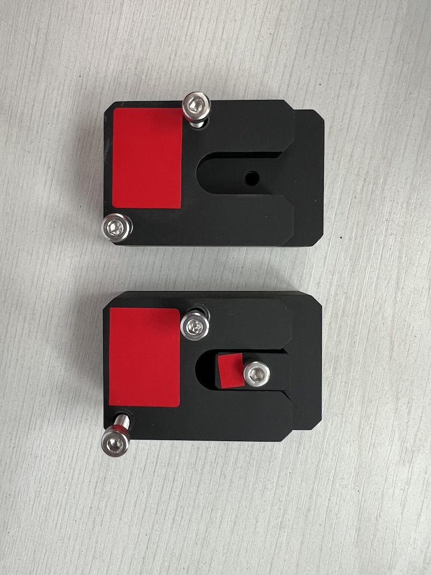
 The small piece can be fixed onto the big piece.
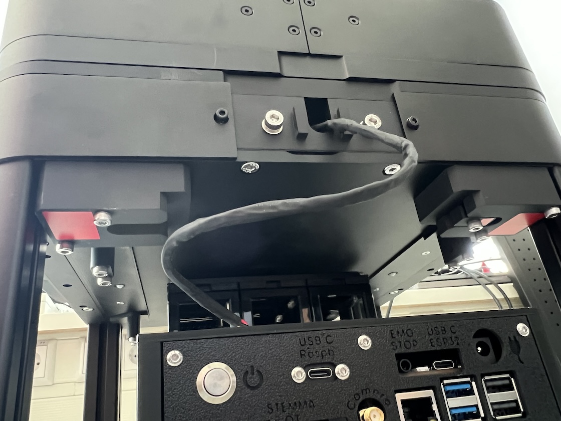
 At the backside of the microscope, above the electrical box, there are screw holes for storing the lock pieces.
Assemble the illumination arm
On the backside of the microscope, there are two screws to mount the illumination arm.
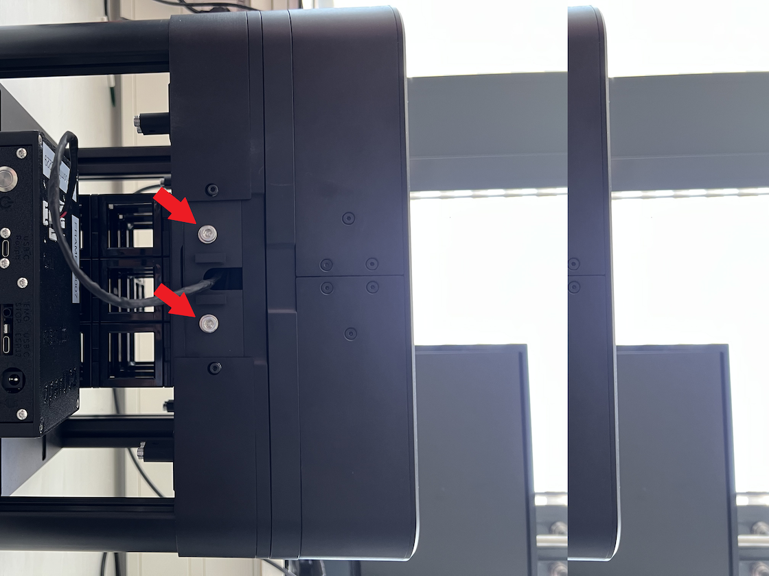 Loose the screws and use them to mount the arm.
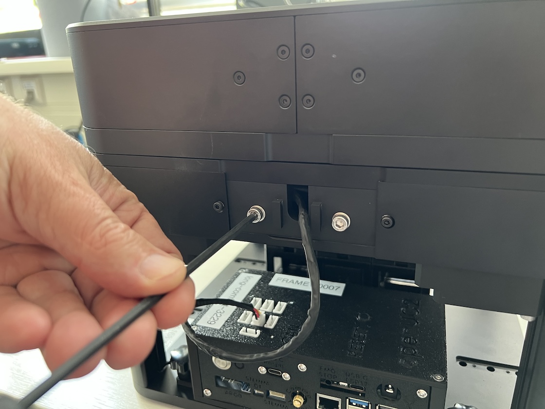 The illumination arm is designed to have the height adjustment ability. It is currently aligned with the lowest position. Tighten the screws after push the arm to the lowest position.
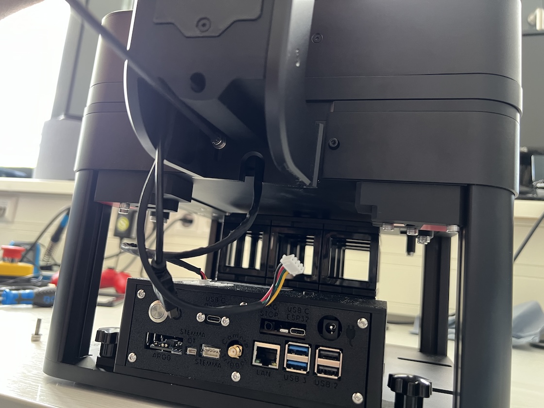
Wiring
Some wires are required to boot the microscope. Two cables hang out from the illumination arm, the JST connector is for CAN communication and should be plug onto any connector on top of the electronics.
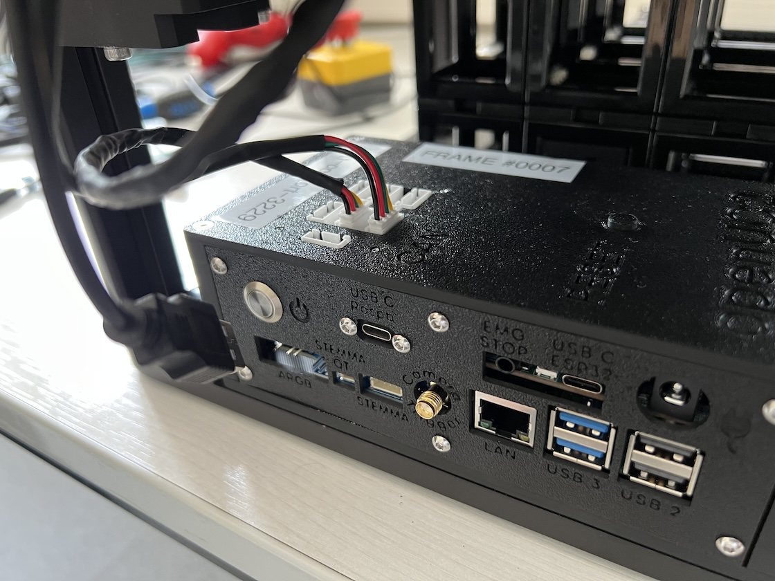
On the electronical panel, there are 2x USB3 and 2x USB2 ports. Use the short 10cm USB cable to connect the ESP32 to the upper USB3 and the camera to the lower USB3. Connect the Emergency stop to the EMC STOP port. Wifi dongle can be plugged to the bottom USB2 port and connect the upper USB2 to USB hub and overview camera, which is the USB cable hanging on the illumination arm.
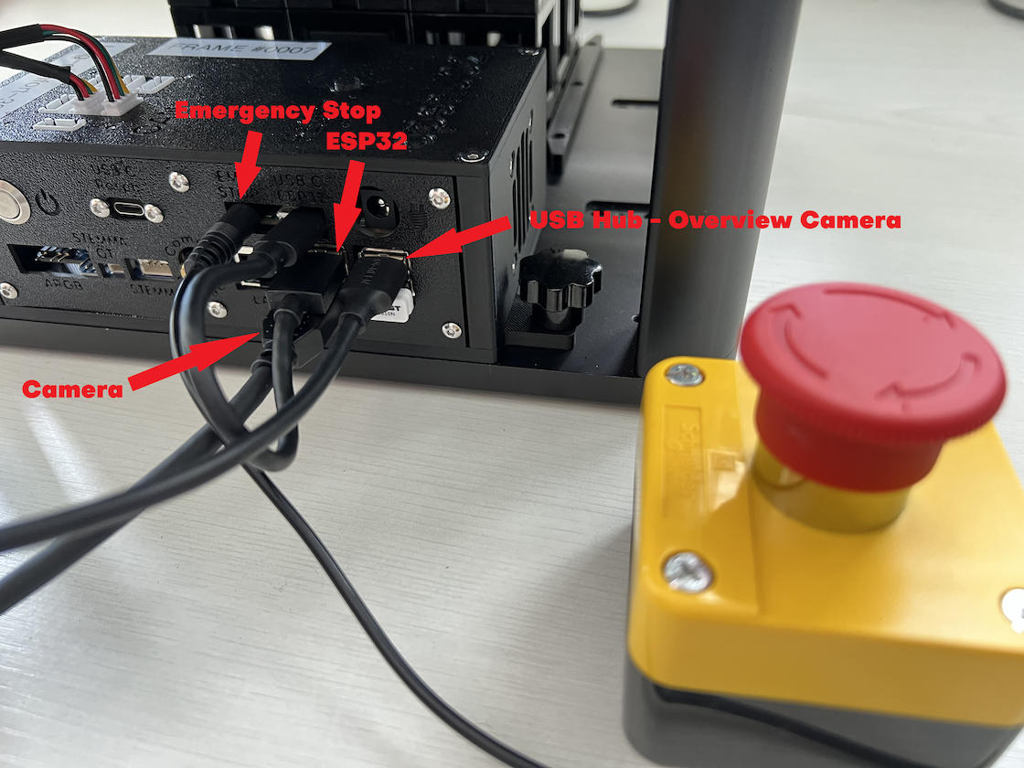
Make sure the emergency stop is on the released position.