Patterned LED illumination with the DLP4710
Status: optics worked out in theory; two relay layouts compared; the prototype starts once the evaluation module is here.
We are building a module that projects light patterns, in blue, green or red, through the FRAME's objective into the sample. It uses TI's DLP4710EVM-LC: a full-HD micromirror chip (1920 x 1080 mirrors at 5.4 µm) in a projector engine with three LEDs. The LEDs are already inside the engine, so no fibre or laser is needed. Unlike our openSIM, which uses coherent laser light to double the resolution, this module is for incoherent patterns: stimulating chosen cells, exciting fluorescence only in a region of interest, bleaching patterns, stripes for optical sectioning, and calibration grids.
What to expect
| colours | blue 455 nm, green 520 nm (broad, used with a band-pass filter), red 624 nm |
| patterns | any pattern from a PC over HDMI, up to 1440 binary patterns per second; stored stripe patterns up to about 2500 per second, with trigger in and out for the camera |
| one DMD pixel at the sample (f180 tube lens) | 1.35 µm (4x), 0.54 µm (10x), 0.27 µm (20x), 0.14 µm (40x) |
| pattern field | 2.6 x 1.5 mm (4x) to 0.26 x 0.15 mm (40x): larger than the camera image with every objective |
| light at the sample | blue, estimated: about 0.6 W/cm² with a 10x/0.25, 1.5 W/cm² with a 20x/0.40 (to be measured) |
Each colour comes with its own dichroic and filters (for example a 495 nm long-pass for blue excitation of GFP or GCaMP, or a dual-band dichroic to image GCaMP in blue while stimulating ChrimsonR in red).
The design
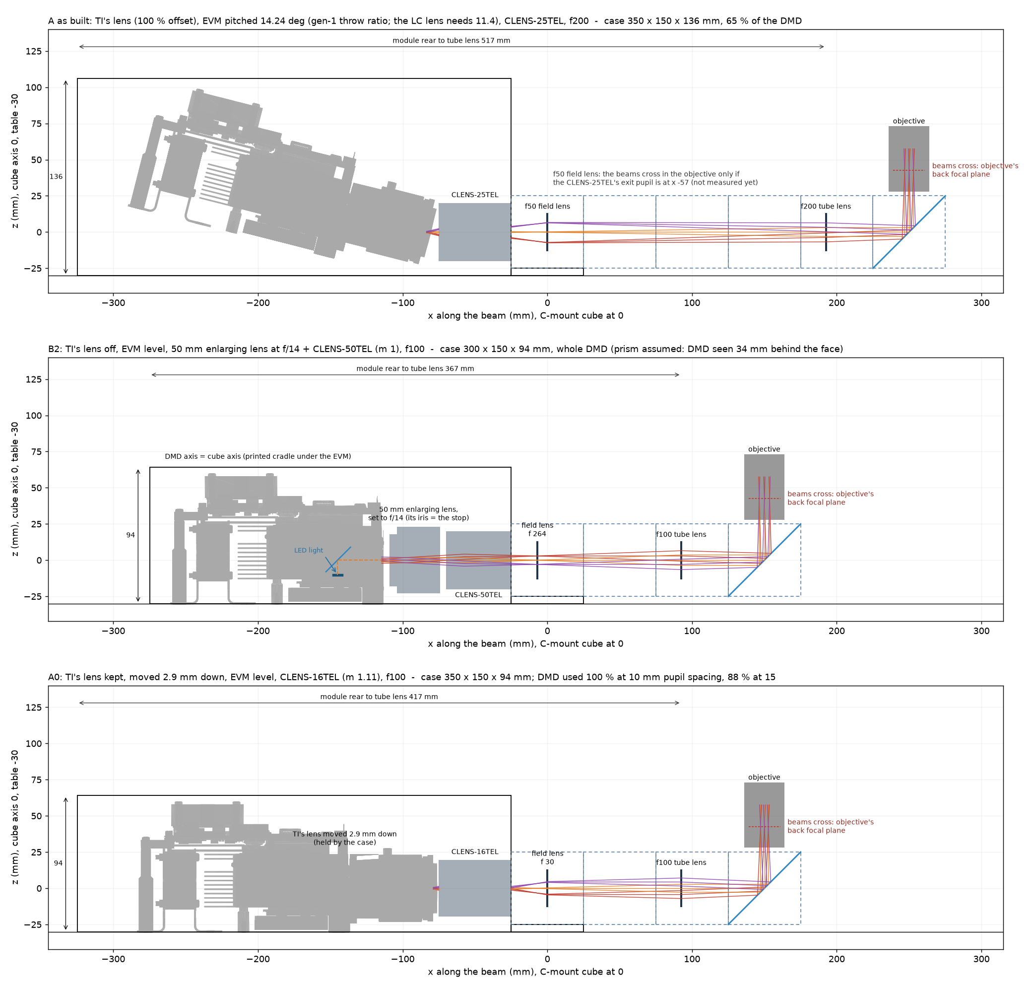
The engine sends its picture through a projection lens that looks up from below the chip (100 % offset), which would force us to tilt the whole module. We compared two ways to get a straight, compact module:
- TI's lens off: a 50 mm enlarging lens and a C-mount lens relay the chip 1:1 into the focus of the FRAME's tube lens. The enlarging lens's own aperture ring matches the light cone to the objective. Module about 300 x 150 x 95 mm.
- TI's lens kept: the case holds TI's lens 2.9 mm lower, centred on the chip, and a 16 mm C-mount lens takes the picture from there. It needs no knowledge of the optics inside the engine.
Inside the engine
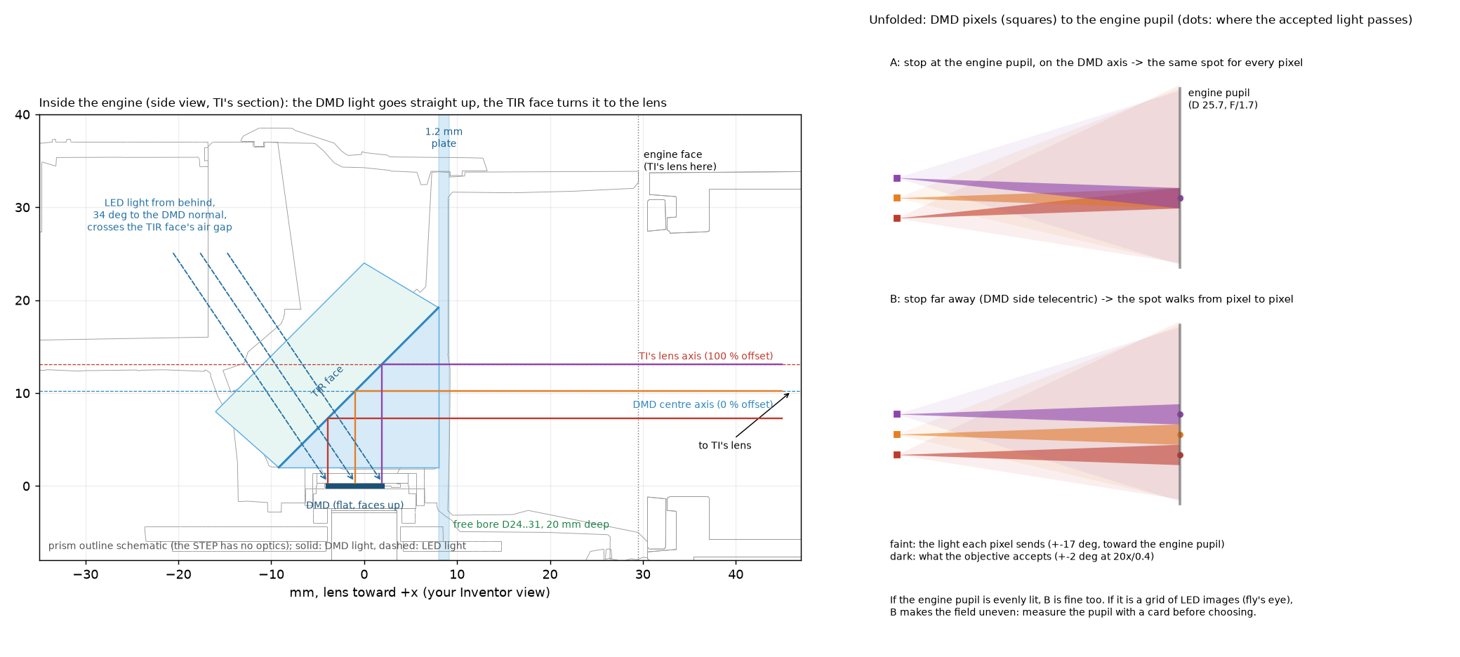
The chip lies flat and sends its light straight up; a prism turns it toward the lens, while the LED light comes in from behind at 34° through the same prism. Each pixel sends a wide cone, of which the microscope uses only a narrow part. Where we put the aperture decides whether every pixel uses the same part of that cone, which keeps the field evenly lit.
In the FRAME
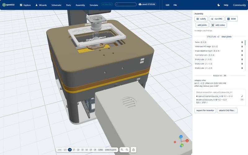
A placeholder of the module already sits in the FRAME configurator, in front of the OPM, for quotes and planning.
Next: measure the engine's light cone and the chip's depth on the real module, choose the layout, then design the case.